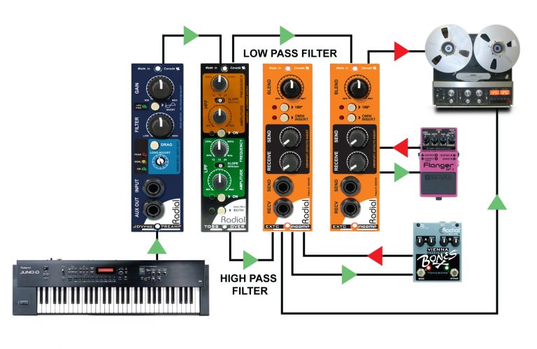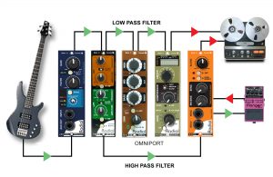
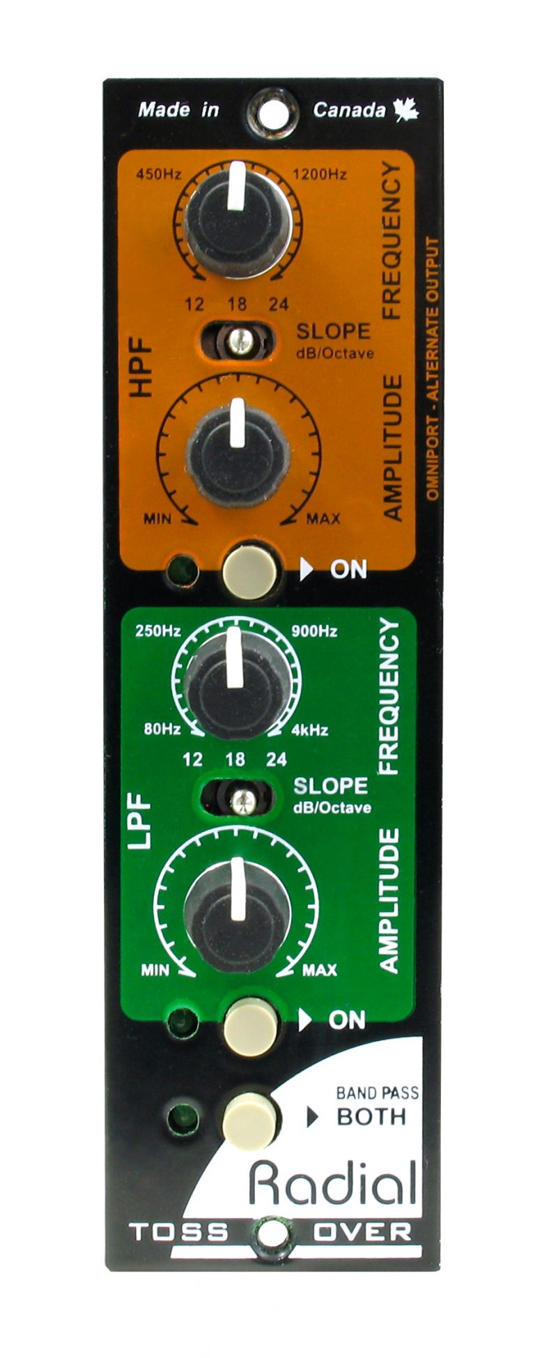
HPF
High pass filter section, used to adjust the high frequency output frequency, slope and amplitude. Wired in series after the low-pass filter.
Frequency
Used to adjust the high frequency cut-off point above which the signal will be allowed to pass.
Slope
Three position switch sets the crossover slope for 12dB, 18dB or 24dB per octave for gentle, medium and intense filter effect.
Amplitude
Used to adjust the output level of the signal after it passes through the high pass filter.
On
Turns on the high pass filter section.
LPF
Low pass filter section, used to control the low frequency output frequency, slope and amplitude. Wired in series before the high-pass filter.
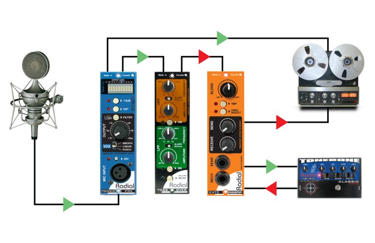
XLR Input
Located on your 500 series power rack is used to feed a balanced line level signal into the Tossover.
Output Select
Mini slider switch above the 15 pin card edge selects which of the two filter outputs will be routed to the XLR or the Omniport when using the Tossover with a Workhorse.
Omniport
¼” TRS connector (found on Radial Workhorse power racks) is the alternate output. When the low pass filter is assigned to the XLR, the high pass filter output automatically gets assigned to the Omniport.
Band Pass (Both)
Combines the two filters in series to create a band pass effect. Set the output select switch to high-pass as the two filters are wired in series.